1D Deployment Rules
Please follow this section to ensure the best positioning performance possible. The listed points below should always be followed during the deployment process.
Rules Overview
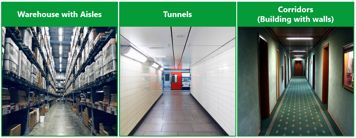
- Sewio support 1D location in a warehouse with aisles, tunnels, and corridors (building with walls)
- 1D can be used with directional anchors (Vista DirectFive) only
- 1D cell consisting of two Vista DirectFive anchors
- Anchors must be placed within the same height (+/- 0.2m); other deployments are not recommended, and they are impractical
- Max. distance between two anchors is 30m
- Anchor tilt is required for higher height placement (6m height→ tilt 8.5°)
- One of the anchors has to be set as a Master
- Parallel 1D cells among the aisles (separated by shelves) should not be closer than 6m and must be aligned
1D Location Supported Use Cases
What is possible to cover with 1D?
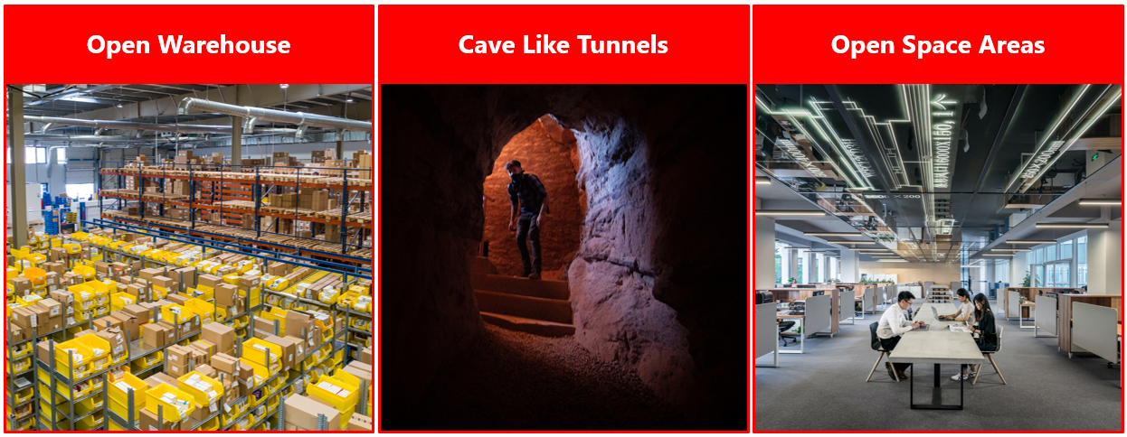
What is not deliverable 1D?
1D and Anchor Vista DirectFive
- 1D Location is available only with Anchors DirectFive.
- Vista DirecFive includes a directional antenna that covers narrowed areas and avoids receiving low-quality tag signals from other localization cells/aisles.
- You need to sustain a proper vertical and horizontal antenna orientation during installation for the best performance. You can see the ideal radiation pattern of the directional antenna (the antenna gain is 90 degrees in the horizontal plane and 36 degrees in the vertical plane) in the picture below.
Anchor Deployment Rules for 1D Location
The 1D location can be deploy in several use cases. Below you can find general rules that you should always follow to achieve the highest accuracy.
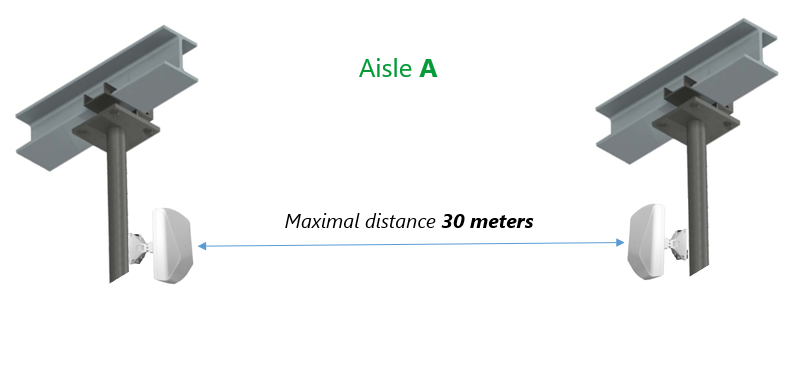
Anchor's distance within the Aisle
The maximal distance between the Anchors is 30 meters in an open environment free of obstacles for 1D localization. The minimal distance between the anchors must be 5 meters but we recommend to have minimal distance of 15 meters to achieve the optimal performance.
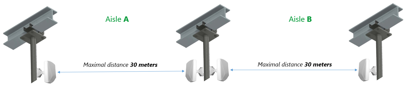
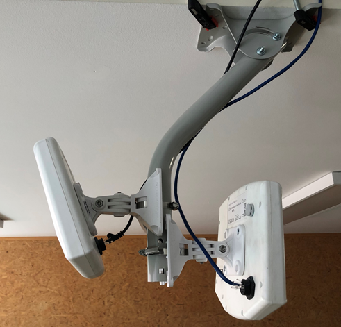
If the aisle for 1D localization is longer than 30 meters, additional pair of anchors must be added. The Anchors in transition area between the Aisles could be mounted on a similar mounting bracket as showed below:
As mentioned above, anchor DirectFive is only anchor type available for 1D location. Anchor Omni brings a limitation and it is NOT possible to use it for the 1D location.
Parallel Aisles
If you consider deploying two parallel aisles, you must follow minimal distance between the aisles.
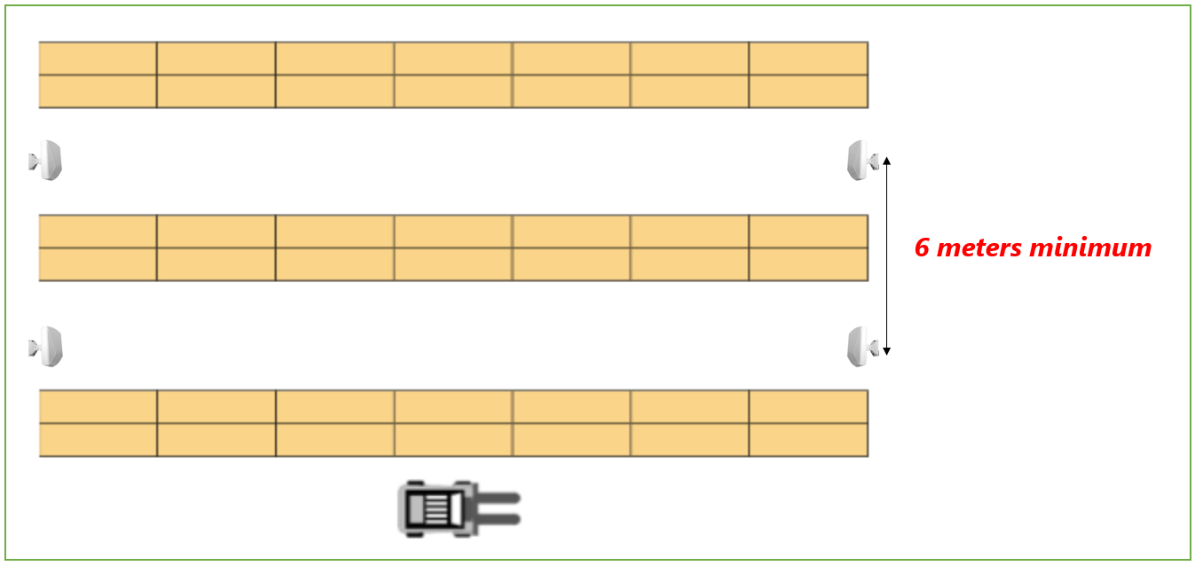
The minimal distance between two 1D aisles is 6 meters in a storage warehouse with the shelves.
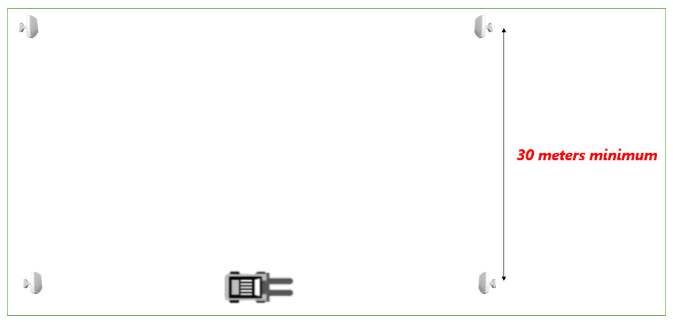
The minimum distance between two parallel aisles in the open area free of obstacles is 30 meters. Any closer distance in open environment could cause intolerable jumps between the parallel aisles.
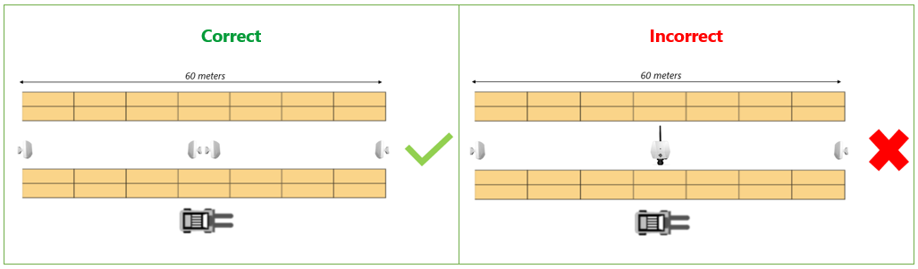
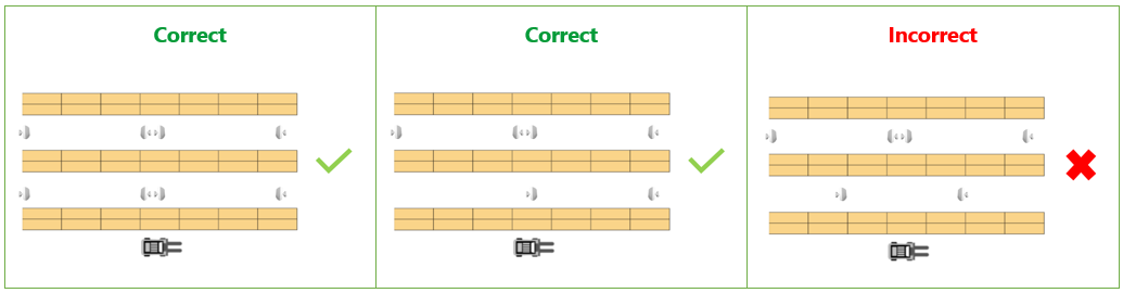
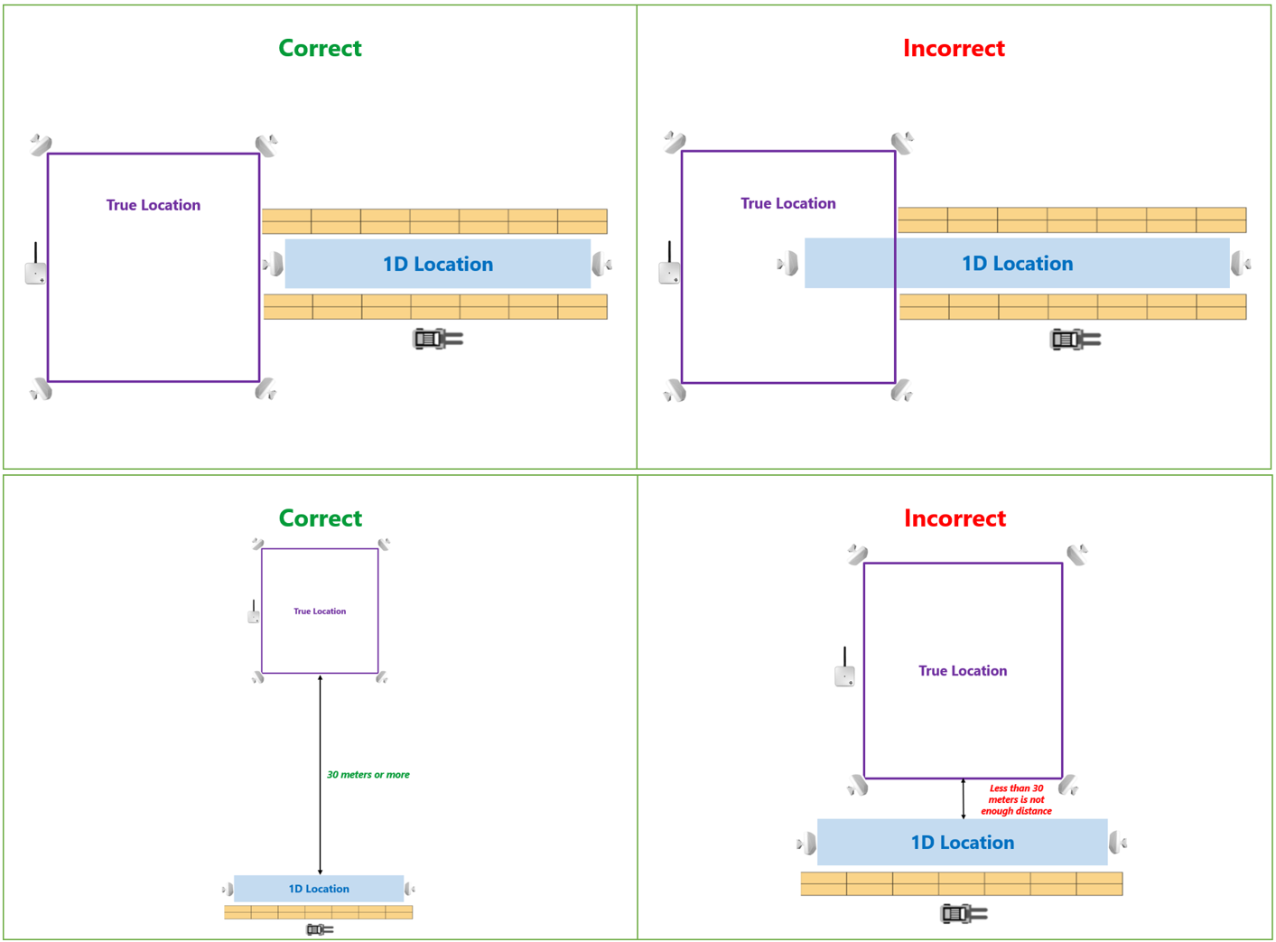
The second rule related to parallel aisles is alignment. See picture below. On the left you can see the correct deployment. The anchors are aligned with anchors deployed in parallel aisle. On the right, the anchors are not aligned which is incorrect deployment. The alignment helps you to avoid unwanted jumps between the aisles.
Maximal height difference between tags and anchors
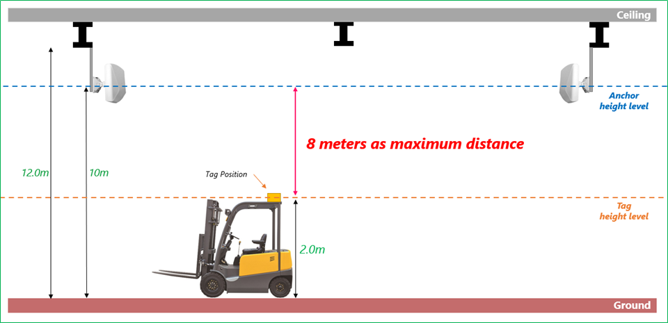
Anchor DirectFive is directional anchors with radiation pattern 90 degrees in the horizontal plane and 36 degrees in the vertical plane. Due to that the area coverage requires specific anchor DirectFive orientation. Based on anchors and tag heights as well as based on the distance between two anchors within 1D cell the anchors are tilted vertically down to keep balance between synchronization and receiving blinks.
Therefore, the height difference between tag and anchors could not be more than 8 meters. With higher height difference you can lose wireless synchronization, or you can lose visibility to tag and not receive any blinks.
Combination 1D and 2D
Having 1D and 2D cells next to each other will cause jumps between them. You have to achieve sufficient radio isolation - spacing between cells → more then 30 meters as a minimum between parallel 1D and 2D localization cells is needed.
If you are considering having 1D and 2D localization cells in the same area/room, the recommended deployment is one cell followed by the other. Make sure that 1D and 2D localization cells do not overlap.
1D Location and Importance of LOS
The synchronization between the Master and the opposite anchor is essential because, without synchronization, the system will not calculate any positions. Equally important is good visibility from Tags to the Anchors forming the aisle. If the tags are not visible to the Anchors, the system will not calculate position correctly, or worse, there would be no position at all.
Synchronization
Anchors must be wirelessly synchronized in order to provide 1D Location functionality. Compared to True Location, the 1D Location depends only on two Anchors which create the Aisle. Therefore, the LOS between the two anchors in the aisle is essential!
The key for successful installation is to have enough space between the lowest obstacle (i.e., an obstacle mounted on the ceiling) and the anchor. It is important to not disturb the radius of the Fresnel Zone between the Anchors.
Radio frequency line of sight is defined by Fresnel Zones which are ellipse-shaped areas between any two radio antennas.
Next two pictures show correct and incorrect installation to achieve LOS for good synchronization:
- Correct = Radius of the Fresnel Zone is not disturbed by any obstacle. The Anchors are installed in a sufficient distance from the cable tray.
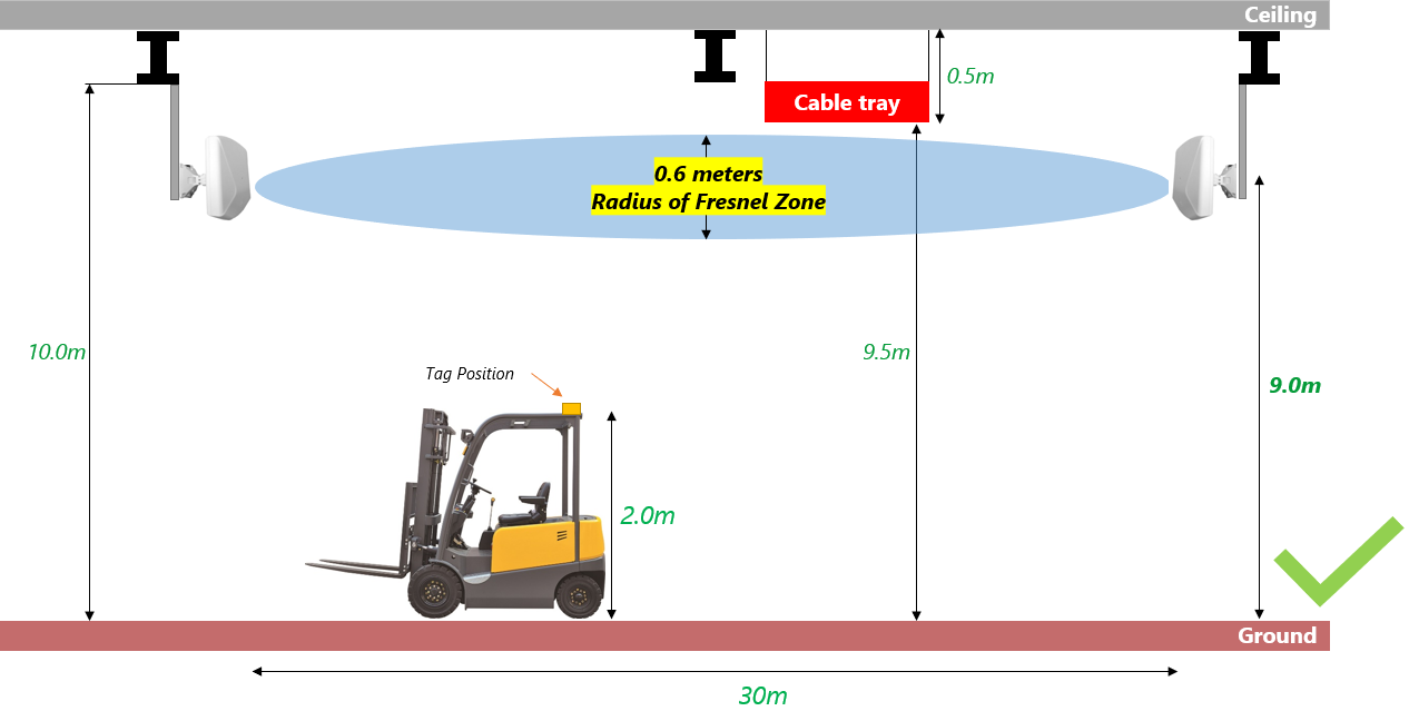
- Incorrect = Radius of the Fresnel Zone is disturbed by an obstacle (cable tray). The Anchors are installed too close below the cable tray which behaves as obstacle for correct synchronization.

Industrial environment includes many obstacles below the ceiling. It is not only about the cable tray as you can see in the example. There could be also beams, pipes, ventilation system, lightning, cranes, and many others.
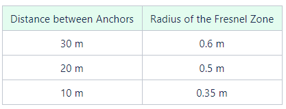
Below you can find a table with few examples of the distance between the two Anchors and its related radius of the Fresnel Zone at its widest point:
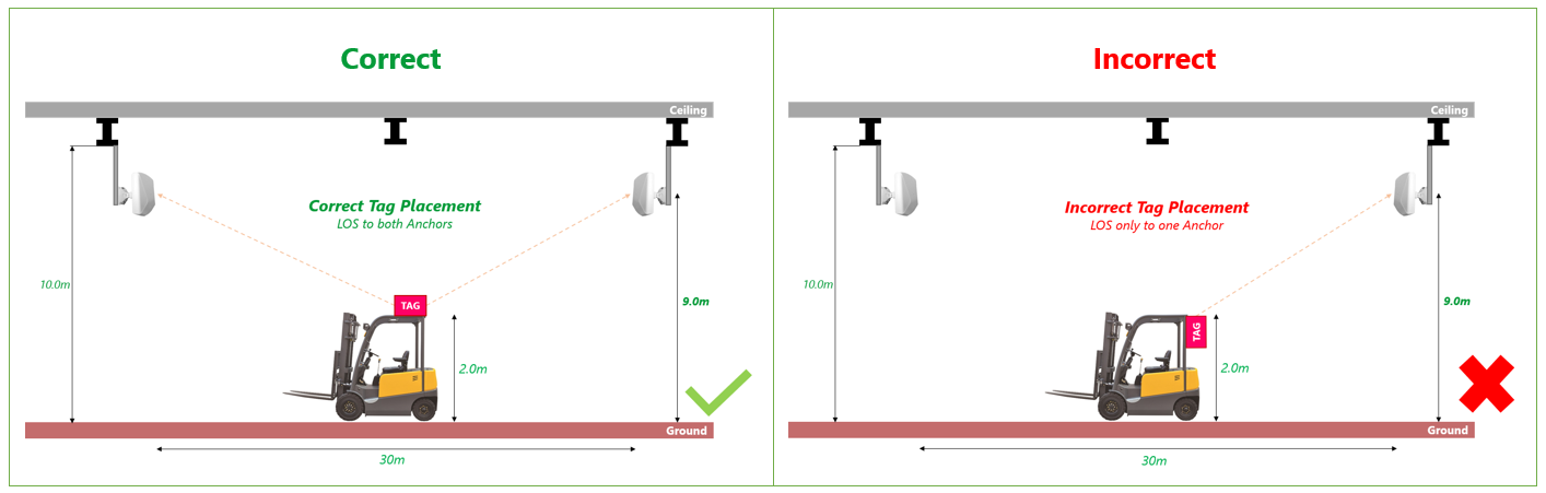
Tag Placement
Always consider the Tag placement with good LOS to both anchors within the aisle. The 1D Location depends only on two Anchors which create the aisle. Therefore, if the Tag has no LOS to both anchors, it is not possible to calculate the position.
More details about the Tag placement you can find in section Tag Deployment Rules.
Vertical Antenna Orientation
It is important to properly orient the anchor vertically. In most cases, it should be tilted down to the ground. The angle of the tilt depends on the anchor’s height and the aisle length.
Consider the following example. We have an Aisle with length 30 meters. The anchors are placed 6 meters high and are oriented towards each other. We know the height of a Tag will be 1.5 meters for this case. It gave us 4.5 meters height difference between the Tag and the Anchors. The Anchor should be pointed to the Tag height below the opposite anchor. The tilt is approximately 8.5 degrees. Of course, the higher the anchors are mounted the more the anchors need to be tilted and vice versa. In other words, the goal is to tilt the anchors such that they will provide good: 1) Synchronization (Anchor to Anchor communication) and 2) Blink reception (Tag to Anchor visibility).

Few examples in table below:
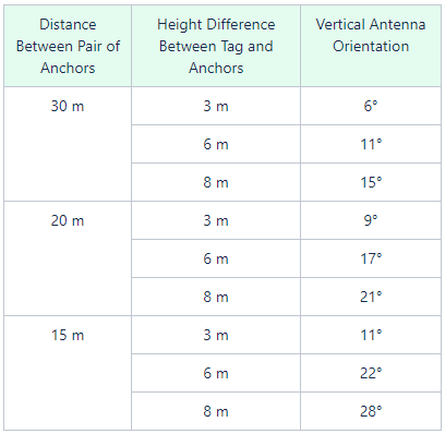
When the anchor is tilted to its maximum, the signal might not reach the opposite anchor, and this could disrupt the synchronization of the anchors. On the other hand, tilting the anchors too little may cause that the main lobe of the signal will be pointed towards the opposite wall rather than the location area where the Tags move.
On this page: