Mixed Deployment
In some installation, it is recommended to use a combination of both antenna types.
Example 1 - Environment with obstacles
In the most cases the environment will be not be open and some obstacle will occur there. Let's follow the example from previous page for cell with dimensions 25 x 20 meters with anchors installed on columns 6 meters high.
If we deploy Anchors Vista DirectFive as on the picture below, the bottom-left anchor will receive the signal from the top-left anchor on the edge of top-left anchor's radiation pattern.
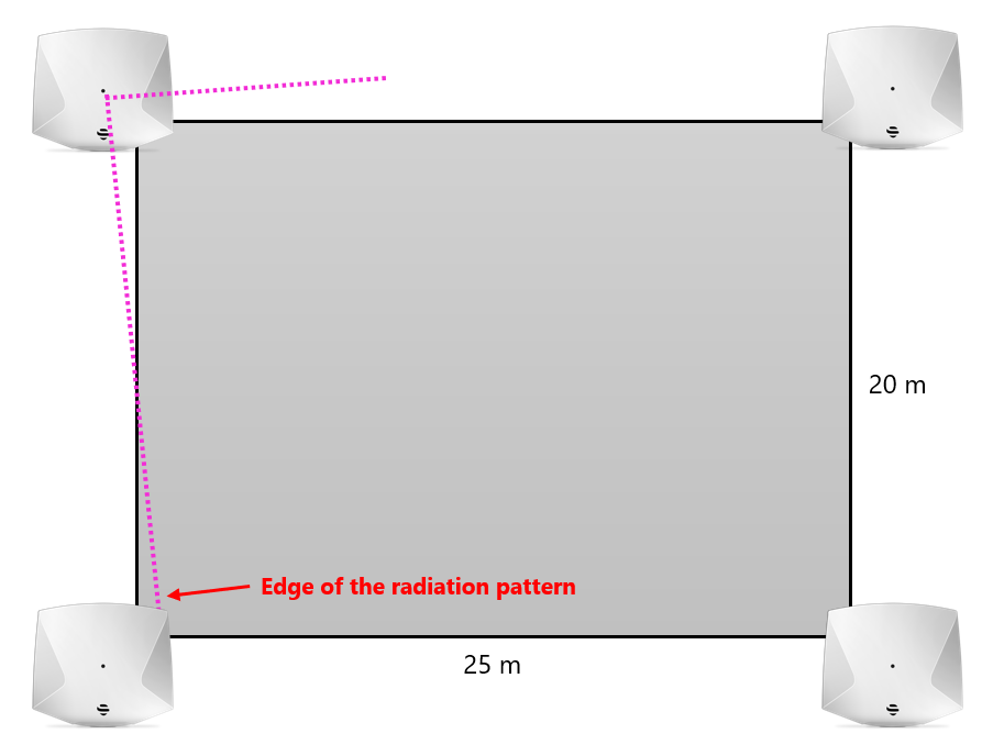
With some obstacles in the area, the received signal quality could not be good. Therefore, to achieve the best synchronization, we should add one more anchor. The Anchor Vista Omni will do the job perfectly and helps to get better synchronization and position calculation for this case.
Even if the installation position in the middle of the cell may seem to be the best position for the anchor, the better position of the anchor is on the longest edge of the cell. Position in the middle is very good for anchor synchronization but when calculating the tag position, it can create an issue in form of jumps.
Example 2 - cell with dimensions 40 x 10 meters
Consider cell with dimensions 40 x 10 meters and anchors installed 3 meters high on columns. This deployment requires six anchors → 4x Anchor Vista DirectFive and 2x Anchor Vista Omni.
In this case, the Anchor Vista DirectFive will be tilted by 5 degree to the ground. Because distance between far ends is 40 meters, the horizontal rotation will be 20 degree. The other Anchors DirectFive in the corners will be vertically and horizontally rotated the same. The Anchors Vista Omni will be in the middle of the longest edges of the cell. Since they are placed in the middle, they will have a good synchronization with the anchors on the edges and will be able to receive blinks from tags in their vicinity.
Example 3 - Complicated Environment
In a more dense and complicated environment, typically in industry, both antenna types can be used simultaneously to cover different parts of the installation based on their attributes.
In the example bellow, we can see that the omnidirectional antennas are used in the smaller spaces with a typical grid of 15×15 meters. On the other hand, the more open corridor with 25 meters distance between the anchors would be impossible to cover with omnidirectional antennas. Here, the directional antennas are used to cover the longer distance.

Antenna Comparison
In some cases, both omnidirectional and directional antennas can be used to cover the same area. However, there are several scenarios where the directional antenna has several advantages over omnidirectional. Below are some examples.
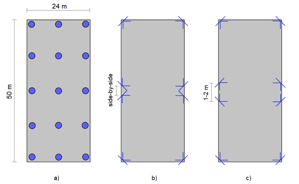
In the example the same area (a long corridor) is covered by both types of anchors. Since the maximum grid for omnidirectional antennas in an open environment is 15×15 meters and the width of the location area is 24 meters, additional row of anchors must be put in the middle on the figure a). This increases the cabling and installation costs.
Another solution to such a scenario is using the directional antennas. In the figure b) and c), we can see that by using a much smaller number of anchors (approximately half) with directional antennas, the same space can be adequately covered. The advantages are both smaller number of anchors and lesser cabling (less cables also means a significant cost reduction) and there is also no need to install the anchors in the middle of the location area, which can sometimes be problematic.
The above figures show two possible directional antenna deployments.
Figure b) represents deployment without overlapping of location cells. Anchors are physically placed next to each other. This type of deployment leads to a smaller total amount of anchors needed to cover area (compared to deployment with Anchor Omni), but a small instability of the tag position may occur at the border between the location cells.
Figure c) represents deployment where location cells overlap. Anchors in the middle are physically placed to face each other. Due to overlapping cells the tag position should be more stable when the tag moves from one cell to another. To ensure correct synchronization the anchors facing each other in the middle should be in the different heights → it avoids shielding effect.
On this page: