Spatial Rotation Determination
The spatial 3D rotation is calculated and sent via UWB link to the server, data are exposed to the user via the API.
Tag Piccolino is equipped with accelerometer only. Due to this fact only tilt of the tag can be calculated, also the non-gravitational acceleration highly affects the result.
Tag iMU can provide much more accurate spatial rotation data, since it is calculated by data fusion over accelerometer, gyroscope, and magnetometer sensors.
Let’s have a look on each sensor separately:
Accelerometer
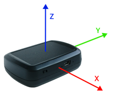
This sensor can be used for calculation of rotation due to gravitational acceleration. If the tag is placed on the flat surface, the gravitational acceleration of 1 g will be observed in the vertical axis. In the other axes zero acceleration will be observed. It means that we obtain an acceleration vector of [0, 0, 1] g. If the Tag is rotated, the vector is rotated too. From the vector rotation, the tilt can be determined. It is the rotation around X and Y axes of the tag. Rotation around the z-axis cannot be calculated from the accelerometer data.
Advantages
- low power consumption
Disadvantages
- sensitive to non-gravitational acceleration including vibrations
- it is impossible to calculate the rotation around the vertical axis
Gyroscope
The gyroscope output are the angular velocities around the three orthogonal axes. By integrating angular velocities, relative rotation can be calculated around all three spatial axes. Theoretically, only the gyroscope could be used to calculate the spatial rotation. But calculated rotation is valid only in short term, due to gyroscope’s inherent drift, which adds a cumulative error to the calculation.
Advantages
- the spatial rotation around all axes can be calculated
- data are not affected by external interference
Disadvantages
- high power consumption
- only relative rotation can be calculated
- short-term reliability of the result
Magnetometer
The magnetometer output is magnetic field strength in three orthogonal axes. Due to the presence of geomagnetic field, it is possible to make an electronic compass. By using magnetometer, the rotation around two axes which are orthogonal to the geomagnetic field vector can be calculated. However, the varying inclination of the magnetic field vector at different locations on Earth is a significant barrier. Therefore, data from the magnetometer can be used only for calculation of the rotation around the vertical axis, on the condition that the tag is in a horizontal position. Moreover, the result may be corrupted by magnetic interference caused by permanent magnets or electromagnetic induction.
Advantages
- Low power consumption
Disadvantages
- Sensitive to magnetic interference
- Rotation around one axis only can be generally used
Sensor Data Fusion
The drawbacks of each inertial sensor above can be suppressed by using the sensor data fusion:
Accelerometer + Magnetometer
By using data from these two sensors, spatial orientation can be calculated around all three spatial axes. However, the effect of non-gravity acceleration and magnetic interference will not be suppressed.
Accelerometer + Gyroscope
Using accelerometer data, gyroscope drift can be eliminated around horizontal axes. When using a complementary filter, the effect of non-gravity acceleration can be suppressed. However, the gyroscope drifts around the vertical axis and remains uncompensated and the rotation around this axis can still be calculated only relatively to the starting position.
Magnetometer + Gyroscope
In this case, the drift around the vertical axis will be suppressed, but drift around other axes not. Similarly to accelerometer + gyroscope fusion, the complementary filter can be used to suppress magnetic interference effect. Rotation around horizontal axes will be calculated only relatively to starting rotation.
Accelerometer + Gyroscope + Magnetometer
Fusion of data from all three sensor is the best solution for spatial rotation estimation. Non-gravitational acceleration effect and magnetic interference can be suppressed by using data from gyroscope. On the contrary drift of gyroscope can be compensated by data from the accelerometer and magnetometer. Data from accelerometer and magnetometer can also be used to calculate the reference rotation instead of starting position.
Spatial Rotation Representation
The calculated rotation can be sent to the server as unit quaternion or as sequence of Tait – Bryan angles. It is highly recommended to use quaternion representation, since the Tait – Bryan angles have irremovable gimbal lock issue.
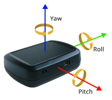
Tait – Bryan angles
Sequence of calculated angles must be applied in order yaw – pitch – roll (z – y – x) when rotation is displayed.
Unit Quaternions
Quaternion is sent in fixed point format (Q8) and is converted back to floating point format on the server. Because of this fact, it is recommended that the quaternion should be normalized again before its application to a rotated object. In JSON output the quaternions members are in order [q0, q1, q2, q3] which represents [-y, -z, -x, w]
Spatial rotation determination can be set by using console or via Wireless Config.