Presence Detection
On this page
Introduction
Presence Detection provides possibility to reduce number of anchors within given area. Areas where just “presence” information is enough, just single anchor is needed. Once the sub-meter so-called “True Location” accuracy is required more anchors must be added. RTLS Studio enables to combine Presence Detection mode with True Location (localization) mode. However this can be applied on only specific use-cases.
Please read further about the details of applicability and limitations for Presence Detection feature.
Watch related video tutorial:
Presence Detection Limitations and Use Cases
Presence Detection cannot rely on precise time-of-flight UWB signal measurement, therefore received signal strength (RSSI) is used instead. However, RSSI is not really correlated with the distance and it is highly affected by the environment. This highly affects stability of measurement, an accuracy and brings several limitations.
True Location requires more dense anchors infrastructure than just Presence Detection but provides accurate and reliable measurement. Nevertheless, in areas where just presence information is enough; cost might be optimized. Please do not use Presence Detection anchors in radio range of True Location anchors!
Here is a comparison table:
True Location | Presence Detection | |
Number of Anchors Required | >= 4 | 1 |
Accuracy | Sub-meter | Just presence info |
API | [x,y,z] of Tag is reported | [x,y,z] of Anchor with best signal strength to Tag is reported. |
Stability | High | Low – highly dependent on environment |
Presence Detection deployment rules:
- Anchor(s) set to Presence Detection mode cannot be close to anchor(s) set in True Location. Their separation must be via thick wall or at least 15 - 25 m, otherwise threshold tuning might be required to avoid tag flickering.
- Separation between Presence Detection anchors should be also at least 15 m, otherwise position can jump back and forth between neighboring anchors.
Examples:
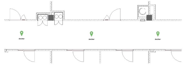
- Scenario: Hallways, Tunnels – where just coarse position is required and direction of Tags. All anchors set to Presence Detection mode. Anchor separation should be at least 15 - 25m.
- Scenario: Mixed topology – entrance is covered with presence anchor, while right room has True Location with four anchors. This could be implemented if anchor in Presence Detection area does not reach anchors in localization cell via UWB. They are separated either via walls or distance.

- Receiving data from Tags. Some applications requires to obtain battery levels on some particular spot or just receive a sensor data.
- Room identification based on Presence Detection – not recommended. The penetration of the UWB signal through the wall may not be constant. Thus putting single anchor per room would not provide reliable solution.
Technical Details
The basic condition for the Presence Detection is to receive blink from Tag on at least one anchor. The anchor might not be synchronized.
Presence Detection is automatically initiated once it is not possible to calculate the precise position. These situations occur in two cases:
- position calculation can’t be started - lack of Tag blinks, no Master Anchor found, no or low-quality synchronization
- calculation of position failed, e.g. due to a large error in the calculation.
Furthermore, it is necessary that the anchor that received the blink has its position set – that means the anchor is assigned to the plan and had the coordinates X, Y and optionally Z.
If the ‘Height Filter’ is also set, the anchor must be at the permitted height. For example: Tag blink received by anchor A1 and A2. Anchor A2 is located higher floor then the tag, so it is excluded from the calculation.
Note: If both anchors are on a higher floor than the tag, the anchors will be excluded and thus not position is reported.
Coordinates of Presence Detection
Position received in API from Presence Detection anchor reports the same parameters as anchor in True Location mode:
Positioning data: posX, posY, at, CLR, numberOfAnchors, posZ
Sensor data (optionally): quaternion, acc, gyro, mag, etc.
posX and posY is the position of the anchor, which is considered to be closest to the tag.
CLR – confidence level - has a value for Presence Detection greater than 9990.
Currently, two codes are used:
- 9999 – Position calculation can’t be started.
- 9998 – Calculation of position failed.
Calculation of Presence Detection
The output of the Presence Detection (PD) algorithm is the position of the anchor that is most likely closest to the tag. This is determined by two parameters:
- The distance of the last tag position from the individual anchors that caught the blink. The last position is the last precise position, otherwise the last PD position. If no such position is available, the distance calculation parameter is ignored.
- RSSI on individual anchors. The higher the value, the better.
Both of these parameters have equivalent priority. For the PD position, it is possible to calculate the Z-axis coordinate, if both the anchor and the tag incorporates barometer.
Configuration of Presence Detection
The following options are available for Presence Detection:
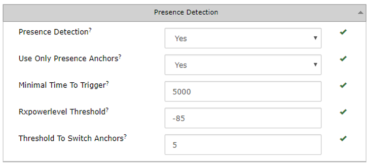
Presence Detection – Global Presence Detection functionality enable/disable.
Use Only Presence Anchors – if set to Yes, only anchors explicitly set in "Presence" localization mode are used for PD. If set to No, then aslo anchors set in "True Location" mode can report position using PD. The anchor configured in the “True Location” mode calculates the position using PD mode only if it is not possible to calculate the "True Location" position and after the "Minimal Time to Trigger" has elapsed.
Minimal Time to Trigger – The hysteresis in milliseconds to switch from True Location mode to Presence Detection mode. By setting the value of 0, the tag will immediately report PD position as soon as it is impossible to calculate the precise position. Thanks to this parameter, one can prevent frequent jumps because of alternation between True Location and Presence Detection mode. This might look like erratically jumps from precise position to position of any anchor.
Note: Hysteresis for switch from precise position to PD position is not defined.
Rxpowerlevel Threshold – Only anchors that have received a blink with RSSI better than this parameter can be used to determine PD position. This makes it possible to limit the distance to which PD is activated - RSSI values less than -80 are mostly in the immediate vicinity of the anchor.
Threshold To Switch Anchors – The tag changes its PD position only if the RSSI on the second anchor is improved by at least that value. As a result, the stability of the PD position will increase, and the tag will not jump once it is within the range of two anchors.
Set Anchor to Presence Detection mode only
Anchor can be set to be used for Presence Detection only and will ignored for True Location mode.
This setting is done in RTLS Manager -> Anchors Summary tab -> Localization Mode dropdown menu.

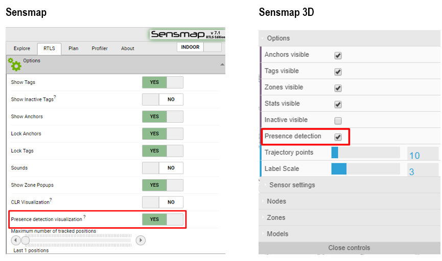
Enable Presence Detection Visualization in Sensmap and 3D Sensmap
Once Presence Detection functionality is enabled within RTLS Manager, you may need also to enable it in visualization in Sensmap or 3D Sensmap. The following figure shows highlighted controls to allow visualization of presence detecting in the Sensmap and Sensmap 3D.