FAQ - System
Question List
General Section
What is the accuracy of the system? What parameters influence the accuracy the most?
The accuracy is dependent mostly on the environment and tag & anchor placement. The correct answer is "it depends". Please read more details and practical information about accuracy on our blog post here.
As a rule of thumb positioning accuracy in the industrial environment can be sub-meter or 30 cm for confidence level >R98 or even 10 cm but only for R70. While for clear line-of-sight environment like sports hall it can be down 10 cm for reasonably good confidence level >R90.
Lower confidence level gives lower positioning stability thus additional filtering might be required on RTLS API output so more raw positions from tag must be gathered thus it has a negative impact on latency and battery lifetime.
Can I install the RTLS studio natively on Windows or Linux and where can I download it?
The RTLS Studio is a Linux-based software. For full functionality, we recommend you to install the RTLS Studio on OS Ubuntu 18.04 Server Edition 64-bit (can be downloaded here). On our Sewio Portal, you can download an Install script for the RTLS Studio. You can also find a short Install Guide there as well.
How are the Anchors deployed? Are there any rules for the deployment?
There are several conditions that should be met in order to achieve highest accuracy possible. These conditions are described in detail in the RTLS TDoA kit Install guide or in Advanced Guide. Please follow it closely during the system installation.
How do I find out that server performance is not sufficient for a given RTLS installation?
RTLS Studio software includes performance monitoring tools – see RTLS Studio main menu -> RTLS Monitor. In terms of server performance monitoring, SYSTEM STATUS and NETWORK are most important tabs.
- Using SYSTEM STATUS tab can be easily checked usage of the RAM (window RAM USAGE), current CPU utilization (window CPU UTILIZATION) and average CPU load (window CPU AVG LOAD ). CPU AVG LOAD window visualizes statistics for three different periods – 1, 5 and 15 minutes.
- Insufficient server performance can be identified by the very high values listed in these monitoring windows. CPU INTENSIVE PROCESSES monitoring window allows you to identify applications that use the large portion of system resources (note: please use a circular icon to refresh/reload data).
- CPU/RAM AVG load should not exceed 95% for longer period of time.
- The network traffic load can be checked using the NETWORK tab. UDP PORTS monitoring window – it provides an overview of the queue size and the number of dropped data frames for a particular port. If the server does not provide the necessary performance, typically number of dropped frames is increased.
- Some drops on UDP Port 5001 (Anchor Sync Reports) are acceptable while drops on UDP Port 5100 (Tag Blink Reports) might cause noticeable positioning outages.
How many Anchors are needed to calculate position?
Just like GPS, mathematically three Anchors are enough but, our system need at least four Anchors one is for correction to calculate precise position.
How should the system be set up for 3D localization?
The 3D localization is implemented in the latest via measuring precise atmospheric pressure data. Please read application note here for more information.
Is there a limit on the total number of devices? How large is the maximum area that the system can cover?
There is no limit on the number of devices in the system, which means that the system is fully scalable. This also implies that the location area is also unlimited. The actual limit is the server performance.
Is there a way to measure the position quality (accuracy)?
Position quality can be checked with the Extended Position Information feature in Sensmap. For further information, check the Advanced Guide, section troubleshooting tools and tips.
Is this technology similar to Wi-Fi, Bluetooth etc.?
Just like Bluetooth and Wi-Fi, Ultra Wide Band is a radio technology, however it is quite different from the other technologies. It is strongly resistant to interference and enables very precise positioning, a feat that both Bluetooth and Wi-Fi or other radio-based technologies simply cannot provide.
It utilizes very wide bandwidth (hence the name) typically 20x wider than Wi-Fi.
What is important to consider if I want to define Zones aka GeoFencing.
Before you begin defining the area of the Zone GeoFencing, consider the following:
- What is the refresh interval configured in Tags?
- What is the maximum speed of Tags that passes through the defined area?
- From what directions you can enter and exit the Zone?
- How will data (notifications) about this Zone be used?
In general – the RTLS system generates a notification at a time when the Tag enters or exits the defined Zone. The notification is generated only if at least one position (Blink message) was sent while the Tag was physically located in the defined Zone.
The points I., II. and III. must be taken into account when designing the length of a Zone. Low refresh interval (too long gap between a Blink messages) combined with a small Zone length can lead to a situation where the notification is not generated even if the Tag has passed through the defined Zone. This situation occurs when the Tag is physically located in the Zone area, but the Tag does not send a Blink message at the given moment.
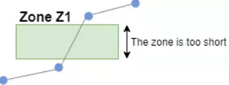
For example – if the refresh interval is 250 ms and the maximum Tag speed is 3 m/s, then the Zone must be at least 1.5 m long. The expression of the calculation using the equation is as follows (more details regarding the calculation procedure are given below):
Minimum zone length = Tag speed [m/s] × ( 2 × Refresh interval [s] )
As for point IV. – if the Zone is intended to identify a relatively small area (e.g. pallet position), then the center of the Zone must be determined based on the physical location of the Tag on the monitored object. For example – the Tag is placed at the edge of the pallet. Then it is not suitable to define the Zone position based on the contour of the pallet. But the position of the Tag must be taken into account.
If multiple Zones are defined next to each other, it is also necessary to take into account the situation where Tag is at the boundary of the Zone (e.g. due to the incorrect physical position of the pallet).
Under certain circumstances, the calculated position of the tag may oscillate slightly. Such a situation may cause several notifications when the Tag enters or exits the Zone. Therefore, it is recommended to use the space between Zones.
An example of the WebSocket API output (subscribe to Zone changes) in the case when the Tag is physically located at the edge of the zone.
| VM101:7 {"body":{"feed_id":"84","zone_id":"357","status":"in","at":"2018-12-06 08:59:18.445"},"resource":"\/zones\/357"} VM101:7 {"body":{"feed_id":"84","zone_id":"357","status":"out","at":"2018-12-06 08:59:18.883"},"resource":"\/zones\/357"} VM101:7 {"body":{"feed_id":"84","zone_id":"357","status":"in","at":"2018-12-06 08:59:19.480"},"resource":"\/zones\/357"} VM101:7 {"body":{"feed_id":"84","zone_id":"357","status":"out","at":"2018-12-06 08:59:21.623"},"resource":"\/zones\/357"} VM101:7 {"body":{"feed_id":"84","zone_id":"357","status":"in","at":"2018-12-06 08:59:21.880"},"resource":"\/zones\/357"} VM101:7 {"body":{"feed_id":"84","zone_id":"357","status":"out","at":"2018-12-06 08:59:23.052"},"resource":"\/zones\/357"} VM101:7 {"body":{"feed_id":"84","zone_id":"357","status":"in","at":"2018-12-06 08:59:23.523"},"resource":"\/zones\/357"} |
Detailed calculation procedure for the Minimum zone length in the above example.
- Refresh interval 250ms represents the reception of 4 positions within 1 second interval, in the ideal scenario.
- However, it is necessary to take into account the impact of the parameter “Random deviation”*, which is a standard part of the Tag configuration. Taking this parameter into account leads to calculation in which a value corresponding to the half of the refresh interval is used. In other words, it represents a situation, in which the system receives 2 Blink messages within a one second interval.
- The maximum Tag speed 3m/s means, that the Tag moves a distance of 3 meters within 1 second.
- The distance divided by the number of received positions determines the minimal Zone length –> 3/2 = 1.5m.
- Refresh interval 250ms represents the reception of 4 positions within 1 second interval, in the ideal scenario.
The calculated minimum Zone length determines the length at which at least one Blink message should be received. No loss of the Blink message is considered in the calculation above. However, some Blink messages are lost (due to the nature of the wireless transmission). In order to increase the robustness of the detection in the Zone, it is strongly recommended to enlarge the Zone (e.g. using coefficient 1.6).
* “Random Deviation” is used to introduce randomized transmission of the Blink message within given time interval. In certain circumstances, the arrival time of two consecutive Blink messages may be longer than the nominal value of the configured refresh interval. In the worst-case scenario, it may happen that the one Blink message is sent at the beginning of the given interval and the next Blink message is sent at the end of the given interval. If we take this worst-case scenario into account, then it is necessary to use such refresh interval value for the calculation, which corresponds to almost half of the refresh interval value defined in the Tag configuration.
What is the frequency and bandwidth of the system? What about interference?
Unlike other overcrowded band like 2.4 or 5 GHz used by WiFi or Bluetooth, the UWB operates at 6.5 GHz which is clear and unoccupied band, thus technology is very suitable for industrial environment where high reliability is demanded.
Network Section
Do you use a server on premises or a cloud connection?
We usually deploy a host server on the customer’s premises for larger deployments. Most customers want to have their sensitive location data stored locally.
How to change the default IP address of RTLS System and Anchors?
It is necessary for both the Anchors and the server to be within the same subnet. Please plan your new IP Address scope accordingly.
First, you’ll need to set up the Anchors’ IP addresses. To do so, go to RTLS Manager -> Anchors Settings and change the IP address, Network Mask and Gateway IP Address. Also, set the RTLS Server IP address as it is the same as RTLS Studio’s IP address.
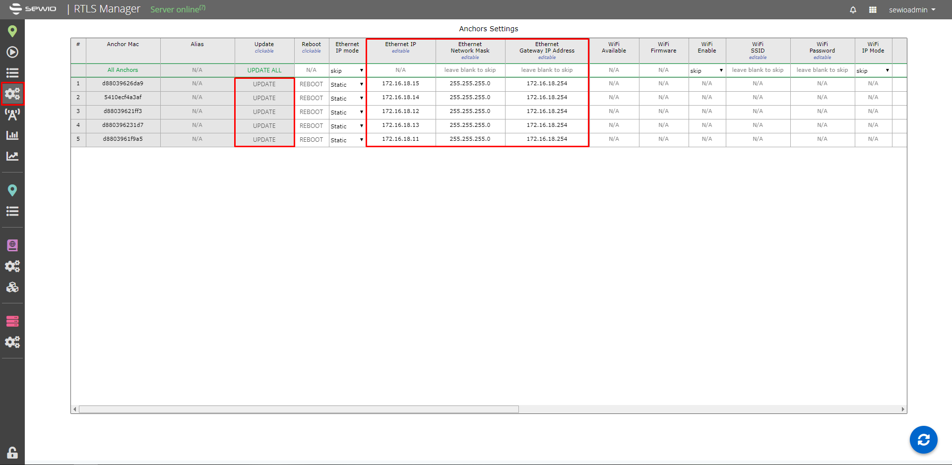
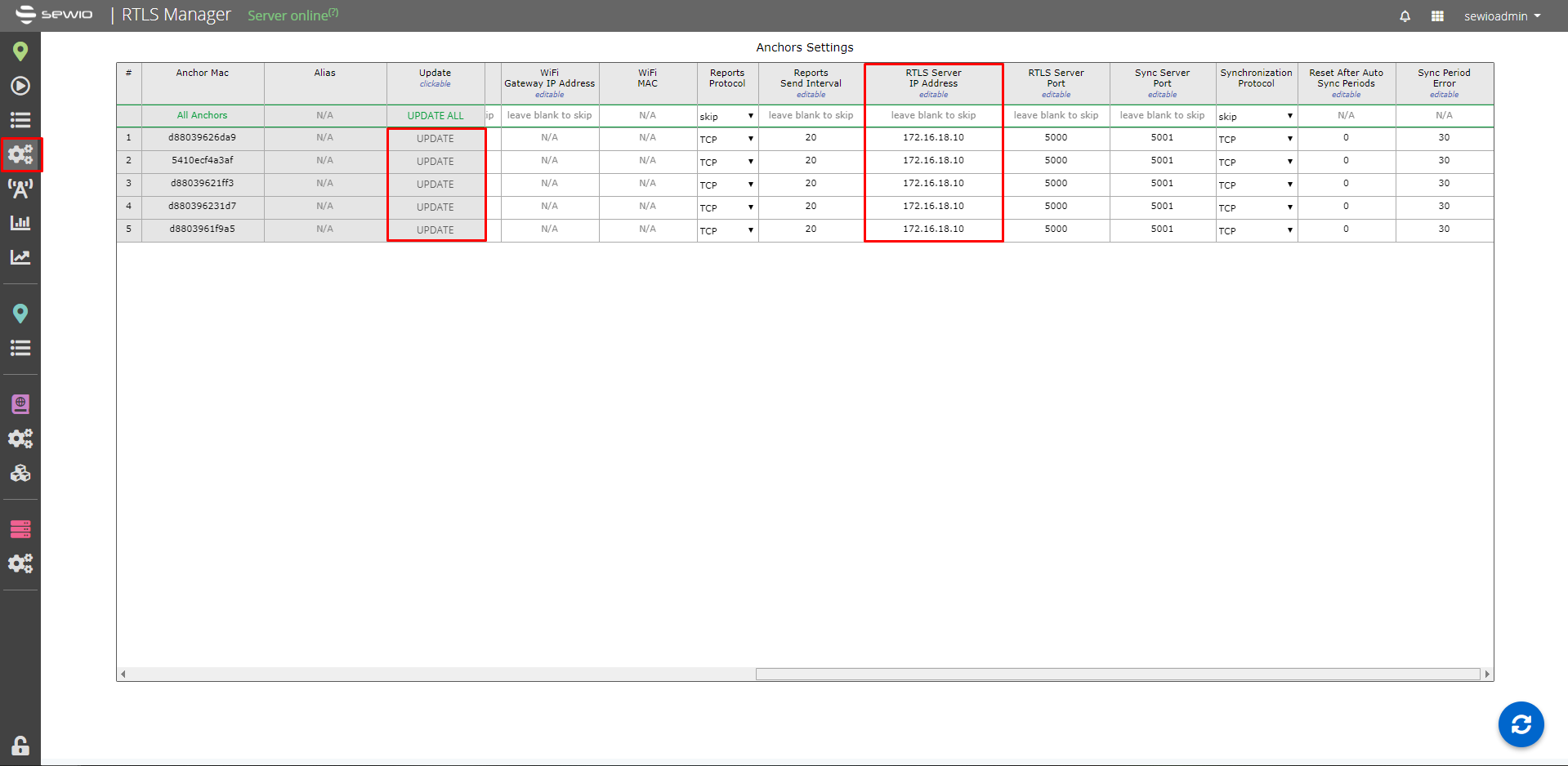
Please do not forget to update every change to the Anchor.
- Then navigate to RTLS Manager -> RTLS Server tab and select “Anchor Synchronization”
Find the UDP Broadcast Address and set it accordingly based on new address scope and netmask:
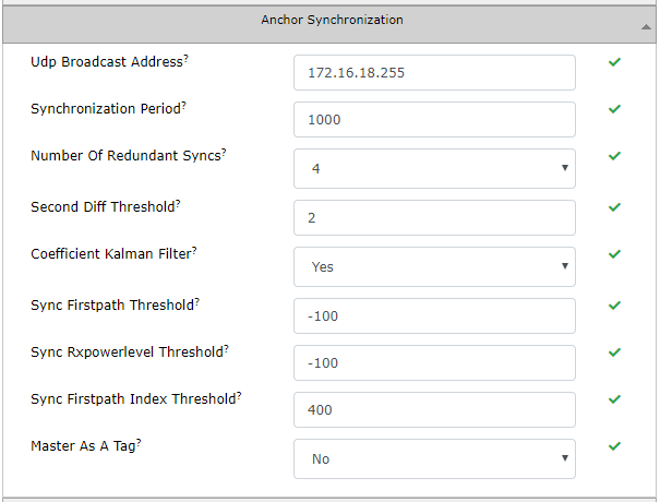
Please don’t forget to press the “Apply and restart RTLS Server” button for the changes to take effect.
- After that, you’ll need to change the IP address of the Ethernet interface on the server. Connect to the server via SSH by using a terminal application (e.g. Putty). The server is still on its default IP address in this step (192.168.225.2).
In case if your RTLS Studio is running on Ubuntu 18.04:
- Login to Ubuntu Server (via SSH) or VirtualBox. The credentials are:
Username: sewiortls
Password: sensmap We will use netplan config file to change the default IP address of server. Edit this file with nano editor:
sudo nano /etc/netplan/50-cloud-init.yaml
- The config file can looks like this:
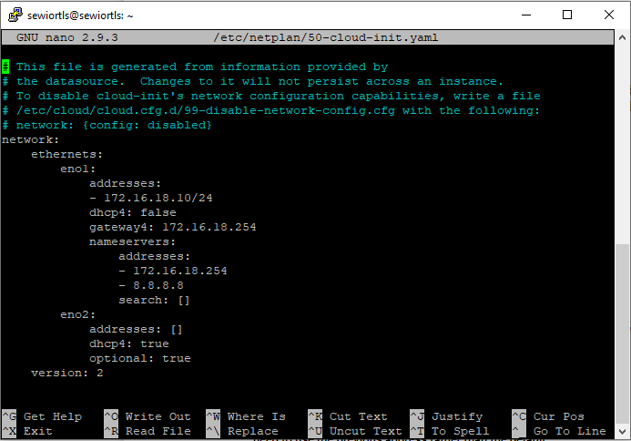
Apply changes:
sudo netplan apply
Verify your configuration:
ifconfig

In case if your RTLS Studio is running on older version of Ubuntu 14.04:
- Login to Ubuntu Server (via SSH) or VirtualBox. The credentials are:
Username: sewiortls
Password: sensmap Edit file config of network interfaces with nano editor:
sudo nano /etc/network/interfaces
- The config file can looks like this:
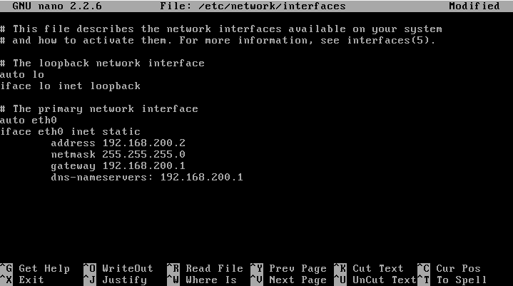
Restart network interface to apply changes:
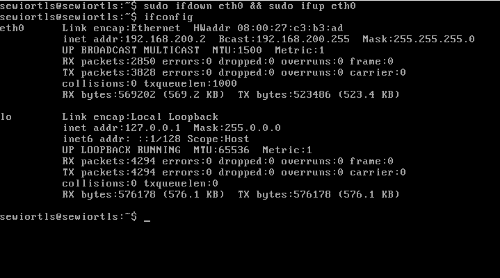
sudo ifdown eth0 && sudo ifup eth0
Verify your configuration:
ifconfig
What kind of Ethernet cables do you use?
We use standard Ethernet Cat5 cabling.
Is it necessary to have the Anchors and the server in one subnet?
From the RTLS Studio v1.6 and Anchors with the firmware >= v3.0 it is possible to have the server and the Anchors in different subnets. However, TCP Sync must be used instead of default UDP sync.
What is important to consider if I want to connect Anchors via WiFi?
There several things that need to be considered when you want to use WiFi as a backhaul connection for Anchors.
- The recommended number of Anchors per AP is up to 5.
- TCP synchronization needs to be set. UDP synchronization will not work with multiple AP.
- The signal strength of WiFi needs to be better than -67 dBm on each Anchor. The WiFi network should be dedicated just for RTLS Anchors.
- AP should be enough powerful, to handle Tags with high RR.
- AP should be connected with the RTLS Server via Ethernet cable, also if you are using multiple AP.
- Powering the Anchors needs to be solved.
- Anchors 1.4 support powering via USB or Passive PoE.
- Anchors Vista line supports powering just via Active PoE.